Debian router with IPv6 prefix delegation, DMZ and dynamic DNS

Recently, I started to set up a Debian Buster based router with IPv6 prefix delegation and two /64 subnets. One subnet is used for desktop clients, the other serves as a demilitarized zone (DMZ) for servers. The Debian router is located behind Fritz.Box home router, which serves as the DSL modem and forwards all external ports to the Debian router. Of course, traditional IPv4 with NAT is also configured. I’m using a dynamic DNS service to access the IPv6 addresses in the DMZ from the Internet. It took me quite some time to figure everything out, therefore I want to share my findings. Of course, this requires that your ISP provides you with more than just one /64 subnet. My ISP provides a /56.

The following diagram illustrates the setup, including interface names on the router:

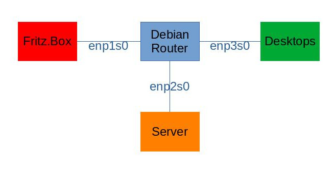
Regarding IPv4, enp1s0 has the address 192.168.0.2/24, enp2s0 has 192.168.1.1/24 and enp3s0 has 192.168.2.1/24.

First, I had to enable prefix delegation in my Fritz.Box. Coming from the IPv4 NAT world this was something new.

Now with prefix delegation enabled in the Fritz.Box, the Debian router needs to set these prefixes to its DMZ and client network interfaces (enp2s0, enp3s0). This can be achieved with the WIDE DHCPv6 client. (https://superuser.com/questions/742792/how-do-i-deploy-ipv6-within-a-lan-using-a-debian-based-router-and-prefix-delegat was very helpful for me.)

On the router, install it (and all other required packages) with

sudo apt install wide-dhcpv6-client dnsmasq iptables-persistent

Then edit

/etc/wide-dhcpv6/dhcp6c.conf

and set its content to

profile default
{
  information-only;
  request domain-name-servers;
  request domain-name;
  script "/etc/wide-dhcpv6/dhcp6c-script";
};

interface enp1s0 {
    send rapid-commit;
    send ia-na 0;
    send ia-pd 0;
};

id-assoc na 0 {
};

id-assoc pd 0 {
    prefix ::/60 infinity;
    prefix-interface enp2s0 {
        sla-len 4;
        sla-id 0;
        ifid 1;
    };
    prefix-interface enp3s0 {
        sla-len 4;
        sla-id 1;
        ifid 1;
    };
};

Also configure the /etc/network/interfaces like this:

source /etc/network/interfaces.d/*

auto lo
iface lo inet loopback

allow-hotplug enp1s0
iface enp1s0 inet dhcp
iface enp1s0 inet6 auto
    # Important to accept delegated prefixes
    post-up sysctl -w net.ipv6.conf.enp1s0.accept_ra=2

allow-hotplug enp2s0
iface enp2s0 inet static
    address 192.168.1.1
    network 192.168.1.0
    netmask 255.255.255.0

allow-hotplug enp3s0
iface enp3s0 inet static
     address 192.168.2.1
     network 192.168.2.0
     netmask 255.255.255.0

Now when connecting enp1s0, the delegated prefixes will automatically be set to the internal facing interfaces. The internal interfaces will receive the addresses $PREFIX::1.

Next, I’m using Dnsmasq on the internal interfaces to provide DNS and IPv6 router advertisements. Add the following lines to the /etc/dnsmasq.conf

# IPv4
dhcp-range=192.168.1.50,192.168.1.150,12h
dhcp-range=192.168.2.50,192.168.2.150,12h
# IPv6
enable-ra
dhcp-range = ::1,constructor:enp2s0, ra-stateless, ra-names, 4h
dhcp-range = ::1,constructor:enp3s0, ra-stateless, ra-names, 4h

To manage inbound and outbound traffic between the different network segments. As is common, the green zone only allows outbound traffic, while the DMZ allows inbound traffic to specified hosts. The following configuration demonstrates how to allow inbound IPv6 traffic to specific hosts. The rule can be extended to specific ports as well. To restore Iptables during boot, I’m using the iptables-persistent package. My /etc/iptables/rules.v4 and /etc/iptables/rules.v6 contain the following lines:

# /etc/iptables/rules.v4
*filter
:INPUT DROP [0:0]
:FORWARD DROP [0:0]
:OUTPUT ACCEPT [81:8253]
-A INPUT -m state --state RELATED,ESTABLISHED -j ACCEPT
-A INPUT -i enp2s0 -j ACCEPT
-A INPUT -i enp3s0 -j ACCEPT
-A INPUT -i lo -j ACCEPT
-A FORWARD -i enp2s0 -j ACCEPT
-A FORWARD -i enp3s0 -j ACCEPT
-A FORWARD -m state --state RELATED,ESTABLISHED -j ACCEPT
COMMIT
*nat
:PREROUTING ACCEPT [44:2803]
:INPUT ACCEPT [23:1484]
:POSTROUTING ACCEPT [0:0]
:OUTPUT ACCEPT [24:1535]
-A POSTROUTING -o enp1s0 -j MASQUERADE
COMMIT
# /etc/iptables/rules.v6
*filter
:INPUT DROP [0:0]
:FORWARD DROP [0:0]
:OUTPUT ACCEPT [175:15496]
-A INPUT -p ipv6-icmp -j ACCEPT
-A INPUT -s fe80::/10 -j ACCEPT
-A INPUT -m state --state RELATED,ESTABLISHED -j ACCEPT
-A INPUT -i enp2s0 -j ACCEPT
-A INPUT -i enp3s0 -j ACCEPT
-A INPUT -i lo -j ACCEPT
-A FORWARD -i enp2s0 -j ACCEPT
-A FORWARD -i enp3s0 -j ACCEPT
-A FORWARD -m state --state RELATED,ESTABLISHED -j ACCEPT
-A FORWARD -d ::2/::ffff:ffff:ffff:ffff -o enp2s0 -p tcp -j ACCEPT
COMMIT

Notice the rule -A FORWARD -d ::2/::ffff:ffff:ffff:ffff -o enp2s0 -p tcp -j ACCEPT. This allows accessing the host in the DMZ from the internet. Now we need to take care that the server in the DMZ always gets the $PREFIX::3 address. This can be done by setting a token with ip. To do this every time the interface is being activated, for example on boot, add the following lines to the /etc/network/interfaces configuration of the server in the DMZ:

iface enp0s31f6 inet6 auto
    pre-up /sbin/ip token set ::2 dev enp0s31f6

To publish the IPv6 address of the server on freedns.afraid.org, I’m using the following crontab line (replace $TOKEN with your private token):

* *    * * *   (IP=$(ip -6 a list dev enp0s31f6 | grep global | awk '{print $2}' | sed 's/\/64//') && wget --no-check-certificate -O - "https://freedns.afraid.org/dynamic/update.php?$TOKEN&address=$IP" >> /tmp/freedns_$HOSTNAME.log 2>&1)

I hope I did not forget any important part. Feel free to ping me if your setup according to this post does not work.

Arduino Spectrometer with TSL1402R

This is an attempt to build a small, lightweight, cheap, diy spectrometer. This was a part of the MINT Girls Regensburg project in 2015 [1]. The spectrometer was designed to work on a Watterott StarterKit Roboter V2 [2]. The robot can connected to a PC via bluetooth. A Python program can be used to remotely control the robot and spectrometer.

All required .stl-files and source code is published under the MIT license on Github [3]. The page about the TSL1402R on Arduino Playground [4] was used as an inspiration.

The spectrometer itself (without Arduino) can be build for less than 40 €.

Spectrometer mounted to robot

Spectrometer mounted to robot

List of required parts

  • 1x Black drinking straw
  • black tape
  • 3D Printer (e.g. black PLA)
  • printable parts (.stl files)
  • 4x M2,5 x 5mm screws + nuts
  • 4x M2,5 x 10mm screws + nuts
  • 2x M4 x 40mm screws + nuts
  • 1x TSL1402R
  • 4x white LEDs
  • 1x perfboard
  • wires, pin cables, hit shrink tube, etc
  • 1x Arduino
  • 1x diffraction grating 1000 lines / mm (cheap source [5])
  • 1x 2N7000 MOSFET

Circuits

TSL1402R on perfboard

TSL1402R on perfboard

Cut out a 30 x 11 mm piece from the perfboard. Solder the TSL1402R onto it and drill to holes into the corners. The holes should be 25 mm apart. The corners will be used to screw the perfboard onto the angled chip holder.

Solder cables to the TSL1402R like shown in Figure 9 of the datasheet [6] (serial connection). Basically connect pin 13 to 10 and 4 to 8.

Then connect the cables to the arduino.

Description Arduino TSL1402R
 Supply voltage +5V  +5V Pin  Pin 1 (VDD)
 Ground  Ground  Pins 5 (GND) and 12 (GND)
 Signal in  Pin 6  Pin 2 (SI1)
 Clock  Pin 2  Pin 3 (CLK)
 Analog out  Pin A3  Pins 4 (AO1) and 8 (AO2)

The white LEDs can be turned on and off with a 2N7000. Connect Pin 7 of the Arduino with the Gate of the 2N7000. The four (parallel) LEDs can be connected to the same voltage source as the Arduino. Make sure to place a fitting resistor between the source and LEDs.

Case

All required parts for the case can be 3D printed, preferably in black. Additionally you need a (black) drinking straw and (black) tape.

After printing all parts, screw the perfboard onto the chip mount, and fixate the chip mount into the bottom of the case. The position of the chip mount can be adjusted to the left and right.

Cut a small rectangular piece from the optical grating and glue (?) it into the grating mount. One screw holds the grating mount to the front panel, the second screw allows for a few degrees of rotation in order to align the grating to the TSL1402R.

Use the 2 screw holes at the bottom of the front panel to fasten it to the bottom of the case.

Use tape to fix the black drinking straw to the front panel. Make sure that the straw is well aligned with the forward facing opening.

Spectrometer assembly

Spectrometer assembly

Additionally you can glue 4 white LEDs into the holes at both sides of the front panel. Make sure that they focus on a point beyond the drinking straw.

Use a bright light source at the end of the straw to align the TSL1402R and the diffraction grating. After you’re finished with the alignment use the two M4 screw to fixate the case cover. Black tape can be used to seal all slits.

Software

Write the RoboterRemoteControl software into your Arduino. If necessary change the pin layout in the configuration section at the beginning of the file.

The Python3 program qtMissionControl can be used to obtain and print simple readouts from the spectrometer. It requires the libraries PyQt4, numpy and matplotlib. The serial port and baudrate have to be set in line 10 and 11 of the source code.

References

[1] http://www.mint-girls-regensburg.de/

[2] http://www.watterott.com/de/StarterKit-Roboter

[3] https://github.com/sven15/arduino-spectrometer

[4] http://playground.arduino.cc/Main/TSL1402R

[5] https://www.3bscientific.de/strichgitter-1000mm-u21874,p_872_1485.html

[6] https://ams.com/jpn/content/download/250165/975693/file/TSL1402R_Datasheet_EN_v1.pdf

Results

Here are some results for comparison. The images are not calibrated to wavelength (yet).

Light sources

result white LED

result white LED

result red LED

result red LED

result blue LED

result blue LED

result neon lamp

result neon lamp

Reflected spectra

yellow object

yellow object

green object

green object

blue object

blue object

Authors

Emma, Franziska, Sven

Using GPS of Ericsson F5521gw in Ubuntu with gpsd

I already tried to use the GPS of my Ericsson F5521gw in my Lenovo L520 a couple of month ago with Ubuntu 12.04 (precise), however it didn’t work out of the box. As the release of 14.04 (trusty) was close, I decided to wait.

However it didn’t work with trusty either. Therefore I decided to dig into the problem. I came up with the following dirty workaround:

First run

$ sudo apt-get install gpsd gpsd-clients wvdial

Edit the /etc/wvdial.conf to look like this:

[Dialer Defaults]
New PPPD = yes
Stupid Mode = 1
Modem Type = USB Modem

[Dialer gps]
Modem = /dev/ttyACM2
Init1 = AT*E2GPSCTL=1,5,1
Init2 = AT*E2GPSNPD

Now we can begin to start gpsd. First establish a connection to your mobile provider with the network manager (upper right corner in Unity).

Then create a pipe somewhere and use wvdial to setup the GPS:

$ mkfifo /root/gps_pipe

$ wvdial gps

The GPS should now transmit data on /dev/ttyACM2. You can have a look at it with “$ cat /dev/ttyACM2”. Stuff the output into the pipe and start gpsd in read only mode:

$ cat /dev/ttyACM2 > /root/gps_pipe

$ gpsd -n -N -D4 -b /root/gps_pipe

If cat stops, just restart cat. If gpsd throws an error, restart it as well. It should work after a couple of attempts. If there is any better solution, you’re welcome to contact me.

[Update] Fix for the cat error: run gpsd with a user that has no write rights on the pipe. I created a pipe in tmp as root

$ mkfifo /tmp/gps_pipe

The pipe should have only read rights for others. Then I can execute gpsd as a normal user and cat does not stop:

$ gpsd -n -N -D4 -b /root/gps_pipe

I used the following ressources:

[1] http://www.thinkwiki.org/wiki/Ericsson_F3507g_Mobile_Broadband_Module

[2] http://forum.ubuntuusers.de/topic/gps-mit-ericsson-mbm-f3705g-einrichten/

[3] http://sourceforge.net/apps/mediawiki/mbm/index.php?title=MBM#GPS_Control_.28mbm-gpsd.29

[4] http://www.tjansson.dk/2009/01/using-the-builtin-gps-in-a-thinkpad-x200-under-linux/

Installing Ubuntu 12.04 server/alternate on computer with NetXtreme ethernet controller

I tried to install the ubuntu server edition of 12.04 on a HP ProLiant DL 385 G1 with a Broadcom NetXtreme BCM5704 ethernet controller. The setup just stops while detecting the hardware. It took me quite some time to figure it out, but here’s what you need to do:

1. disable Floppy controller. Don’t ask me why, it’s definitely weird.

2. copy the tg3_tso.bin corresponding to your kernel version on an USB pen drive in a folder called “tigon” and on the USB pen drive root folder (I’m not sure which location, so just copy it into both). You can get the file from the linux-firmware package. If you already have a running Ubuntu machine, you can find the file in /lib/firmware/tigon

3. Start the Ubuntu alternate/server setup and plug in your usb pen drive as soon as the first dialogue appears.

4. Now everything should work as expected. If the installer doesn’t find the tg3_tso.bin, you can manually mount the USB pen drive and create a symlink of the tg3_tso.bin to /lib/firmware/tigon/tg3_tso.bin

This solution should work for all Debian based setups.